

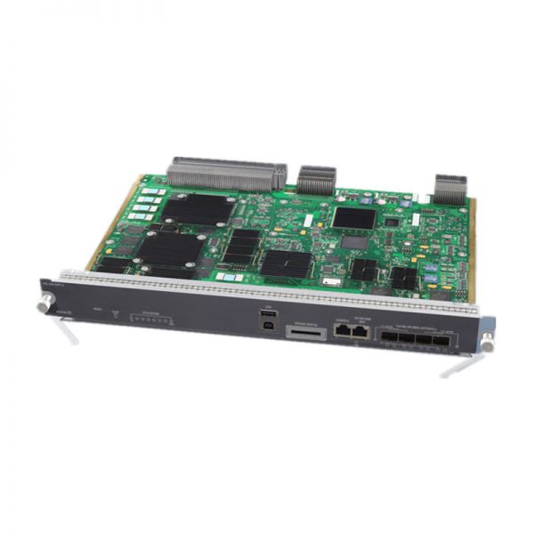
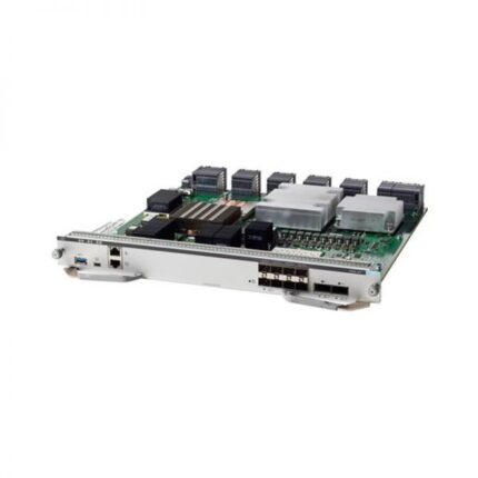
WS-X45-SUP7-E Specification |
|
| Chassis compatibility | All Catalyst 4500 E-series switches |
| Software requirements (minimum) | Refer to your software release notes for the latest software release requirements |
| Chassis slot restrictions | •Catalyst 4503-E: Slot 1 only
•Catalyst 4506-E: Slot 1 only •Catalyst 4507R-E and Catalyst 4507R+E: Slot 3 and slot 4 •Catalyst 4510R-E and Catalyst 4510R+E: Slot 5 and slot 6 |
| Bandwidth per slot | 48-Gbps |
| Memory | 2-GB (upgrade to 4-GB) |
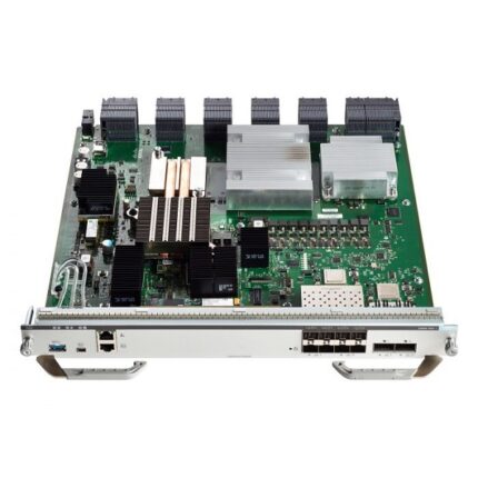
| STATUS LED | The status LED indicates the current health of the supervisor engine and the current software state. |
| RESET switch | The RESET switch is used to reset and restart the switch.
Note Use a paper clip or other small, pointed object to press the RESET switch. |
| ACTIVE SUP LED | The active supervisor engine LED indicates whether the supervisor engine is active or in standby mode in redundant supervisor engine configurations. |
| UTILIZATION LEDs | Eight LEDs indicate (as an approximate percentage) the current traffic load over the backplane. |
| USB connectors | Two USB 2.0 ports are provided. Port 1 operates in device mode (upstream) and port 2 in host mode (downstream). Port 1 has a standard Type B USB connector and can be used as a USB console.Port 2 has a USB type A connector and a standard USB 2.0 device like a flash memory device can plug into this connector. |
| SECURE DIGITAL slot | A standard Secure Data (SD) memory card interface is provided on the front panel |
| CONSOLE port | This is a 10/100/1000 port that uses an RJ-45 connector. The console port allows you th access the switch either locally (with a console terminal) has an RJ-45 connector. The console port allows you to perform the following functions:
•Configure the switch from the CLI •Monitor network statistics and errors •Configure SNMP agent parameters |
| 10/100/1000 MGT port | The Ethernet management port is a Layer 3 host port to which you can connect a PC. You can use the Ethernet management port instead of the switch console port for network management. When managing a switch, connect the PC to the Ethernet management port on a Catalyst 4500 E-series switch.
Note When connecting a PC to the Ethernet management port, you must assign an IP address. |
| LINK LED | The 10/100/1000 MGT port has a link LED associated with it. |
| 1G/10G UPLINKS (SFP/SFP+) ports | The Supervisor Engine 7-E has four 1-G or 10-G ports that use either SFP transceivers or SFP+ transceivers. |
| Uplink port LEDs | Each of the four uplink ports has two LEDs associated with it. One LED displays port status when a 1-GB SFP transceiver is installed in the port socket. The second LED displays uplink port status when a 10-GB SFP+ transceiver is installed in the port socket. |
| Power requirement | 302 W |
| Operating temperature | Certified for operation: 32° to 104°F (0° to 40°C)
•Designed and tested for operation: 32° to 130°F (0° to 55°C) |
| Humidity (RH) ambient (noncondensing) | 10 to 90% |
| Operating altitude | Certified for operation: 0 to 6500 ft (0 to 2000 m)
•Designed and tested for operation: -200 to 10,000 ft (-60 to 3000 m) |
| Operating temperature | Certified for operation: 32° to 104°F (0° to 40°C)
•Designed and tested for operation: 32° to 130°F (0° to 55°C) |
|
Supervisor Engine 7-E Front Panel LEDs |
|
| STATUS | The STATUS LED indicates the status of he supervisor engine.
Green—All diagniostic tests have passed Orange—System boot or a diagnostic test is in progress. Red—A diagnostic test failed. Off—The supervisor engine is disabled or is not powered up. |
| ACTIVE SUP | Indicates whether the supervisor engine is active or standby.
Green—Supervisor engine is active (in redundant supervisor engine configurations) Off—Supervisor engine is in standby mode (in redundant supervisor engine configurations) |
| UTILIZATION | When the switch is operational, the eight utilization LEDs indicate the current traffic load over the backplane as an approximate percentage value. Each LED lit green indicates approximately 12.5 percent of load. |
| MGT port | Indicates the status of the 10/100/1000BASE-T Ethernet management port
Green—The link is operational. Orange—The link is disabled by user. Flashing orange—The power-on self-test indicates a faulty port. Off—No signal is detected or there is a link configuration failure. |
| Uplink link | Indicates the status of the uplink port
Green—The link is operational. Orange—The link is disabled by user. Flashing orange—The power-on self-test indicates a faulty port. Off—No signal is detected or there is a link configuration failure. |
FREE SHIPPING
For Selected Orders.
SECURE PAYMENT
Cash on Delivery.
24/7 SUPPORT
Unlimited help desk.
100% SAFE
View our benefits.
FREE RETURNS
Track or cancel orders.